



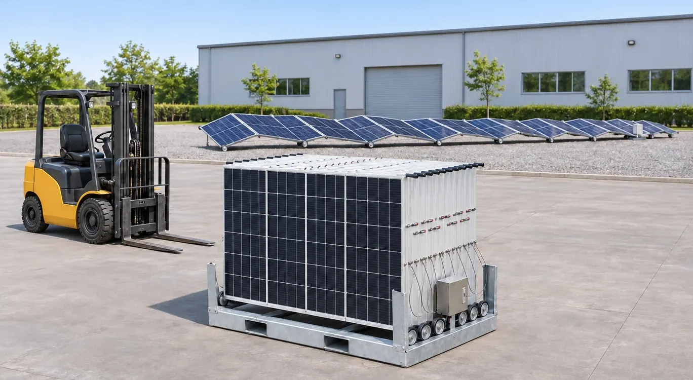
Illustration of a folded pallet-based array, a parked forklift and a separate deployed array.
Mobile solar array deployment starts before the delivery vehicle arrives. Confirm the lifted configuration, forklift requirements and site layout, then agree on the mechanical deployment method, electrical handover and stowage plan. A prepared site needs space for unloading, the open array, protected cable routes and the next collection.
This guide focuses on a pallet-based Mobile Fold-Out Solar Array System with hinged PV sections that open along the ground. It supports planning for temporary construction sites, remote facilities and other projects that expect to relocate their equipment. To select the equipment format first, compare fold-out arrays, solar trailers and solar containers.
Mobile Solar Array Deployment at a Glance
For a deployable solar array, use the selected model’s handling drawing, operating instructions and electrical design to agree on the work. Assign the lift-truck operator, deployment lead and electrical lead before delivery. At a small site, one person may hold several roles if appropriately qualified and authorized.
Prefabricated solar arrays reduce work at the installation site, but site resources still depend on the design. SunWize’s folding platform uses a pallet format, while the larger 5B Maverick describes pre-wired ground-mount blocks and telehandler-based deployment. Obtain the method for the exact unit being delivered.
Stage | Prepare | Check before moving on |
|---|---|---|
Delivery planning | Model documents, delivery details and unloading responsibilities | Actual lifted mass, load center and approved handling arrangement |
Site preparation | Access route, staging area, deployment corridor and cable routes | Ground and clearances match equipment and project requirements |
Unloading and positioning | Suitable handling equipment and controlled work area | Inspection completed; array positioned for its approved opening method |
Mechanical deployment | Model instructions, tools and weather conditions | Supports, locks and moving sections checked as specified |
Electrical handover | Compatible receiving equipment and commissioning plan | Electrical team records required checks before operation |
Stowage and collection | Shutdown arrangements, retraction conditions and freight plan | Folded unit, cables, locks and transport restraints checked |
Confirm the Handling Data Before Delivery
A base with fork-entry pockets provides a handling interface. Choosing a forklift also requires the load configuration, center of gravity, entry arrangement and the truck’s capacity under the actual lifting conditions. Solar array forklift handling should be planned from the approved drawing and the forklift data plate.
Information to request | Why the receiving team needs it |
|---|---|
Model and lifted configuration | Packaging, accessories and equipment attached during lifting can change the load |
Total lifted mass and center of gravity | Establish the actual load and its position relative to the forks |
Approved fork-entry drawing | Identify entry direction, pocket dimensions, fork engagement and required support |
Forklift and attachment details | Check capacity for the actual load center, lift height and attachment configuration |
Handling and locking instructions | Confirm the approved state of folded sections, latches and loose parts during a move |
Delivery and collection arrangement | Check vehicle access, unloading position, ground and responsibilities at both sites |
Do not select a forklift by comparing its nominal tonnage with the array weight alone. Load center and attachments can affect capacity. Ask the truck manufacturer or authorized dealer to verify the combination when the available documentation does not establish suitability. Toyota explains the relationship between load center and capacity.
Arrange a trained, evaluated operator familiar with the truck and site. Keep personnel clear of the handling area, inspect the load and use the approved support points. The OSHA load-handling guide and operator-training guidance provide U.S. reference material; the responsible team should confirm the requirements applicable to its project.
Plan the Site Layout Before Unloading
Draw the route from the delivery entrance to the final array position and back to the collection point. Include the folded footprint, the full deployed envelope and the space needed while sections move. A mobile solar site layout should also preserve access to controls, electrical equipment and inspection points throughout operation.
Five Areas to Mark on the Site Plan
Area | Planning questions |
|---|---|
Delivery approach | Can the delivery vehicle enter, turn, stop and leave? Are overhead obstructions and visibility addressed? |
Unloading and staging | Is there firm, suitable ground for the loaded handling equipment and folded unit? Where will packaging and tools go? |
Deployment corridor | Does the space cover the array’s entire movement and operating envelope, with the required clearances? |
Electrical and pedestrian routes | Can cables reach the receiving equipment while remaining protected from vehicles, feet and moving sections? |
Recovery and collection route | Can the unit be closed, retrieved and loaded after other site equipment has arrived? |
Check bearing capacity, surface condition, slope and drainage against the handling equipment and array requirements. Small rollers do not establish that a fold-out solar array can travel over any gravel, mud or uneven ground. The supplier should confirm acceptable surfaces, support provisions and the approved deployment method.
The HSE site-layout checklist emphasizes suitable routes and separation of people and vehicles. The solarfold FAQ illustrates why soil, supports, anchors and rails must be considered for the particular system. Treat such design details as questions for the selected supplier.
Position, Deploy and Complete the Electrical Handover
Before opening the array, the deployment lead should confirm that the unit is undamaged, the corridor is clear, the site is controlled and conditions meet the model instructions. The plan should identify how sections move, how people remain clear of moving joints and who confirms the final mechanical condition.
Use the manufacturer-approved deployment method. Do not use a forklift to pull an array open unless that method is explicitly authorized for the unit. Confirm required supports, restraints, locks and cable routing before handing the mechanically deployed array to the electrical team.
Define When the System Is Ready to Operate
Ask suppliers what their deployment-time estimate includes: unloading, mechanical opening, electrical connection, checks or commissioning. Nomad’s product FAQ includes several of these activities in its stated deployment scope. Record the same start and finish points when comparing proposals.
For a PV array supplied with separate inverter or battery equipment, agree on the electrical interface and the commissioning responsibilities. The electrical lead should review the approved system design, input limits, protection, earthing or bonding, connector identification and test records. The U.S. DOE installation and commissioning guide provides a useful framework for documentation and cable-management checks.
Connector handling requires an established safe electrical condition. Turning off an inverter does not establish that PV cables are de-energized; illuminated PV modules can produce DC voltage. The electrical team must follow the applicable equipment and connector instructions before mating or separating connections. Never disconnect PV connectors under load.
Identify the actual connector manufacturer and series in the supplied documentation. Stäubli’s MA231 instructions cover its specified MC4 connectors, including electrical precautions, cable routing and protection of unmated connectors. A generic “MC4” description does not confirm that this particular connector manual applies to the delivered unit.
Inspect and Secure the Array for Stowage
Plan solar array stowage before the equipment starts operating. Record the model’s operating, deployment and retraction conditions separately, and allow enough time to finish the authorized process before conditions become unsuitable. Assign weather monitoring, the decision to stop and the electrical handover to named people.
Stowage and Transport Checklist
Confirm electrical release. The electrical lead completes the prescribed shutdown, isolation, verification and connection handling for the full system, including any storage or external supply.
Inspect the movement path. Remove obstructions and check the condition of hinges, rollers and supports as required by the model instructions.
Protect cables and connectors. Keep wiring clear of pinch points and moving sections. Retain cables as specified, respect cable bend limits and protect unmated connectors with the correct sealing caps.
Complete authorized retraction. Use the documented sequence, tools and personnel arrangements. Stop and investigate unexpected resistance or damage.
Verify the folded condition. Check all specified locks, latches, retained accessories and the folded envelope before handling.
Prepare for transport. Use the approved lifting and freight-restraint arrangements. Confirm the carrier’s requirements and complete a final inspection before dispatch.
The Trystar GridPak operator manual separates array retraction, load-device stowage and final transit inspection. This is a useful planning pattern. Its controls, weather limits and trailer procedures belong to the GridPak model; obtain the corresponding instructions for the pallet-based unit.
Keep a Deployment and Transport Record
A redeployable solar system benefits from a short record that travels with it. For each move, retain the model and serial number, current drawing revisions, receiving-site layout, equipment checks, electrical handover, identified damage and final transport inspection. Add dated photos of the unit’s condition at dispatch and receipt.
Record who accepted each stage and any unresolved issue. Before the next deployment, check whether the site, truck, attachments, array configuration or electrical equipment has changed. Update the plan where necessary. This makes the solar array transport checklist useful across repeated moves.
Frequently Asked Questions
What size forklift does a mobile solar array need?
Confirm the actual lifted mass, center of gravity, fork-entry requirements, lift height and attachment configuration. Use the array handling drawing and truck capacity information to verify suitability. The array’s weight alone does not determine a suitable forklift rating.
Can a fold-out solar array be deployed on gravel?
It depends on the specified surface and deployment method. Confirm the ground’s bearing capacity, slope, drainage and finish, together with any support or rail requirements. Small rollers do not establish suitability for a particular gravel surface.
How much space is needed for fold-out solar panel deployment?
Request the model’s folded, moving and deployed envelopes. Add unloading space, handling-equipment maneuvering room, equipment access, protected cable routes and the clearances specified for the project. Preserve a route for closing and collecting the array.
When should a mobile solar array be stowed for weather?
Use the selected model’s operating and retraction conditions. The site plan should specify who monitors the forecast, who calls for stowage and how much lead time the approved procedure requires. Obtain the limits for the supplied configuration from the manufacturer.
Does mechanical deployment mean the power system is ready?
Mechanical opening is one stage. The project electrical team still needs to complete the agreed connection, inspection and commissioning work for the array and its receiving equipment before releasing the system for operation.
Request a Deployment Planning Review
For a Hinergy mobile fold-out solar array project, send your delivery location, site sketch, intended array configuration, available handling equipment and receiving inverter or battery details. Identify who will handle unloading, deployment and electrical work so the required model documents and supply scope can be confirmed before shipment.