



A mobile array can arrive as a complete mechanical assembly while supplying only PV DC output. A BESS may contain batteries, power conversion and controls, yet still have no input for raw solar DC. That distinction determines which equipment belongs between them.
This guide explains the checks to agree before buying or deploying a Mobile Fold-Out Solar Array System. It focuses on equipment matching and handover. If you are still choosing a physical format, start with our comparison of fold-out solar arrays, solar trailers and solar containers.
Identify the BESS Input Before Selecting Equipment
Ask for the exact BESS and inverter model numbers, current manuals and a single-line diagram. Identify the intended solar connection point on that diagram rather than assuming that a cabinet marked “energy storage” accepts PV.
There are three important boundaries:
PV input: a designated input with documented voltage, current and power limits, normally feeding an MPPT stage.
Battery connection: a controlled battery-side interface. It is not a substitute for a solar charge controller or a general-purpose PV input.
AC connection: an AC interface whose permitted sources, power direction and operating modes must be specified.
An AC-only BESS normally needs a separate, compatible PV inverter for an AC-coupled solar path. A hybrid inverter with suitable PV inputs may accept the array directly at those inputs. A battery inverter without a PV tracker may require an approved external MPPT arrangement. Confirm the actual architecture with the responsible suppliers.
Also establish the array supply boundary. Specify whether the quotation includes the PV modules, fold-out structure, handling base and DC wiring only, or also selected conversion, storage and control equipment. Assign responsibility for the combined design and commissioning.
Choose a DC-Coupled or AC-Coupled Path
The connection path affects hardware, control and future expansion. Select it around the equipment already owned, the required operating modes and documented compatibility.
Connection path | How the array enters the system | What must be confirmed |
|---|---|---|
Hybrid inverter with PV inputs | Array DC enters the designated MPPT inputs; an approved battery connects to the designated battery interface | Each PV input limit, battery compatibility, operating modes and the inverter's charging and AC ratings |
Separate MPPT solar charger | Array DC enters the charger; its controlled output connects to the approved battery-side arrangement | Battery voltage and chemistry, coordinated charge limits, protection and compatibility with the inverter and BMS |
AC-coupled PV and BESS | Array DC enters a PV inverter; its AC output connects at an approved point in the BESS system | AC architecture, voltage and phase, charging direction, grid-forming capability where needed, and surplus-PV control |
Sungrow's AC/DC coupling overview explains the conversion-path distinction. For a project decision, go further: identify the actual MPPT, charging and control stages. Neither system size nor the label “hybrid” proves compatibility.
An existing PV inverter can make AC coupling worth considering. A new array may suit a DC path when the selected equipment supports it. Compare the complete configuration, including restrictions on backup operation, rather than applying a universal efficiency or cost rule.
Match the Array to Each MPPT Input
Request the as-supplied string diagram for the fold-out array. Record modules in series, parallel strings, any internal combining, and the number of independent output pairs. Several mechanical sections do not necessarily provide several electrically independent strings.
For hybrid inverter PV string sizing, check the following separately.
Input check | Array information to use | Equipment information to confirm |
|---|---|---|
Absolute PV voltage | String open-circuit voltage corrected for the site's minimum design temperature | Maximum permitted PV open-circuit voltage and the manufacturer's required design method |
Operating and start-up voltage | Expected string Vmp across the design cell-temperature range, plus start-up conditions | MPPT operating window, start-up requirements and any voltage-dependent power limits |
Operating current | String Imp and the sum of parallel-string currents on that tracker | Usable input current per MPPT and any manufacturer-approved oversizing or clipping conditions |
Short-circuit current | String Isc, parallel connections and applicable design corrections | Separate PV short-circuit current limit, including any per-input and per-tracker restrictions |
PV power and input allocation | Total rated DC power, power per tracker and the proposed output-to-input mapping | Allowed connected PV power, tracker limits and which connectors share an MPPT |
Cold-weather Voc and hot-weather Vmp answer different questions. Staying below the absolute voltage ceiling does not establish that a short string can operate inside the MPPT window. Likewise, the permitted PV array power is different from the inverter's AC output rating.
The Victron MPPT manual's PV array section shows why equipment-specific voltage and current limits matter. Use the exact selected manual; its values and connection rules do not transfer automatically to another controller.
If a prewired array already combines its strings, obtain written confirmation before changing that arrangement or splitting it between trackers. Keep module characteristics, orientation and shading compatible with the proposed MPPT grouping. The Solis string-design guidance also illustrates the value of a location- and model-specific design report.
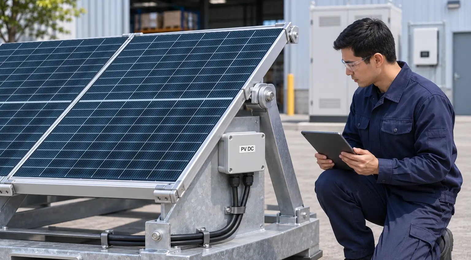
Illustrative interface inspection. A photograph does not establish the actual string configuration or electrical ratings; use the quoted model's documents.
Work Through a String-Sizing Example
The following values are hypothetical teaching inputs, not Hinergy specifications or an approved string design. They demonstrate why voltage, current and power require separate checks.
Assume one module has 500 W rated power, Voc of 50 V, Vmp of 40 V, Imp of 12.5 A and Isc of 13.5 A at standard test conditions. Assume its Voc temperature coefficient is −0.25%/°C and its Vmp coefficient is −0.30%/°C. The design cell temperatures are −10°C minimum and 70°C maximum.
For comparison, assume the proposed PV input permits 500 V maximum open-circuit voltage, a 200–450 V MPPT range, 16 A operating current, 20 A short-circuit current and 6 kW connected PV power on the tracker being considered.
For eight modules in series and one string, a first-pass calculation gives:
Check | Illustrative calculation | Preliminary result |
|---|---|---|
Cold string Voc | 8 × 50 × [1 + (−0.0025 × (−10 − 25))] | 435 V, below the assumed 500 V ceiling |
Hot string Vmp | 8 × 40 × [1 + (−0.0030 × (70 − 25))] | 276.8 V, within the assumed MPPT range |
Cold string Vmp | 8 × 40 × [1 + (−0.0030 × (−10 − 25))] | 353.6 V, within the assumed MPPT range |
One-string current | Imp = 12.5 A; Isc = 13.5 A before required design corrections | Compare separately with 16 A and 20 A |
Connected rated power | 8 × 500 W | 4 kW, below the assumed 6 kW allowance |
The temperature coefficients above are expressed as fractions in the calculations: −0.25% becomes −0.0025. Use the module's Voc and Vmp coefficients or the manufacturer's approved design data; do not substitute the maximum-power temperature coefficient for either voltage coefficient.
Adding a second identical string in parallel on that same tracker leaves the series voltage unchanged but gives 25 A Imp, 27 A Isc before corrections, and 8 kW connected power. Those values exceed this example's assumed limits. An expectation of power clipping does not permit exceeding absolute voltage or short-circuit limits.
This preliminary result still needs the applicable temperature method, correction factors, tolerances, start-up check, protection, cabling and manufacturer approval. If the design cannot pass, select an approved different string arrangement, independently available MPPT inputs or different equipment. Do not alter a supplied mobile array's internal wiring based on the example.
Check Battery and BMS Compatibility
For a DC battery connection, compare the battery's full operating voltage range with the designated battery interface. Nominal voltage alone is insufficient. Confirm usable energy, continuous and peak charge/discharge capability, temperature limits and the effects of state of charge on available power.
For managed lithium batteries, record the exact inverter, battery and BMS models, supported protocol, communication cable requirements and firmware versions. CAN and RS485 describe interfaces; they do not mean that two devices exchange the same messages or implement the same control behavior.
Fronius's battery compatibility matrix demonstrates why compatibility is a model-specific question with software and market conditions. Obtain the selected suppliers' current compatibility documents or written confirmation rather than assuming that a whole brand is interchangeable.
Where several sources can charge the battery, establish how the combined charge is limited. This can include an internal PV charger, external MPPT chargers and charging through the inverter from a generator or grid. Confirm who coordinates the BMS limits and what happens when charging permission changes or communication is lost. For an integrated BESS, the external project interface may be its PCS or EMS rather than a directly accessible battery BMS.
Energy capacity remains a separate calculation. Our construction-site solar and battery sizing guide explains load and reserve inputs; this compatibility check does not establish battery runtime or seasonal recharge performance.
Confirm Off-Grid Control and Recovery
If the system must operate without the utility grid, identify the device that establishes AC voltage and frequency. A conventional grid-following PV inverter does not create that reference by itself. SMA's AC-coupled off-grid overview makes the battery inverter's grid-forming role explicit.
Ask the integrator to document these operating cases:
Battery full and little load: how PV production is reduced or disconnected before charging limits are exceeded.
A large load suddenly stops: how the system handles the immediate surplus while remaining inside equipment limits.
Low state of charge or a shutdown: whether black start is supported, its conditions, and how the system recovers when the AC reference is absent.
Communication or equipment fault: the agreed response, alarms and recovery responsibility.
Generator or utility connection: permitted parallel operation, transfer arrangements, export/reverse-power control and the designated connection point.
AC-coupled control may use approved frequency-based regulation, communications or controlled disconnection. The selected products must support the intended method. Victron's AC-coupling guidance illustrates that limits, configuration and recovery provisions are product-specific. Its sizing rules are not universal BESS ratios.
A generator socket does not prove that simultaneous solar and generator operation is supported. Confirm the approved system arrangement and reverse-power behavior. For operating patterns, camp services and existing diesel equipment, use our remote industrial site and field camp power guide.
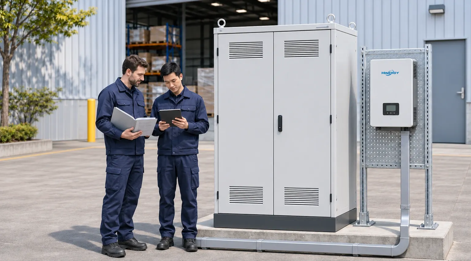
Illustrative control review. Off-grid operation, charging limits and recovery behavior require confirmation for the actual equipment combination.
Protect the Cable Route Through Every Move
Electrical compatibility must survive transport, deployment and stowage. The array drawing should identify cable movement across hinges, approved bend radii, strain relief, protected routing and connector parking positions. Keep cable loops clear of pinch points, wheels and handling pockets throughout the approved movement.
Record connector manufacturer, type and approved mating combination. A similar housing or an “MC4-compatible” description is not proof of an approved pair. Stäubli's cross-mating explanation addresses this distinction.
Define DC cable length, voltage drop, current capacity, environmental suitability, isolation and protection in the project design. The integrator must also resolve protective bonding, earthing, neutral arrangements and AC distribution for the operating modes. Connector fit alone does not answer those questions.
Use the approved isolation and operating procedure before moving or stowing equipment. PV modules can remain energized in light, and PV connectors must not be unplugged under load. Installation and electrical verification belong with qualified personnel following the selected equipment manuals and local requirements.
Our mobile solar array deployment and stowage guide covers receiving, site layout and handling. Keep its deployment record with the electrical configuration and inspection record.
Record Compatibility Before Commissioning
Agree the handover evidence before the equipment reaches the site. The record should connect the delivered hardware to the approved configuration and show who completed each verification.
Record | What it should identify |
|---|---|
Equipment and drawings | Exact array, module, inverter, BESS and BMS models; current datasheets; approved single-line and string diagrams |
PV input allocation | Series/parallel layout, independent outputs, combining and the MPPT assigned to each output |
Limits and settings | Temperature calculations, input limits, approved battery settings, firmware and required communication configuration |
Electrical verification | Qualified-person records for the applicable polarity, protection, bonding, cable and installation checks |
Functional acceptance | Agreed observations for charging, loads, surplus PV, backup/transfer, shutdown, restart and relevant faults |
Relocation and support | Post-move inspection, approved operating instructions, open issues, responsible parties and support contacts |
A successful start-up is one observation. It does not establish behavior at a full battery, after an abrupt load change or following a low-SOC shutdown. Use an agreed commissioning plan covering the project's required modes and record unresolved conditions before acceptance.
Send an Array Integration RFQ
Give the array supplier and integrator the same technical brief. Mark each major item as included, optional, already installed or supplied by another party.
RFQ item | Information to provide |
|---|---|
Application and operating modes | Location, season, temporary or repeated deployment, grid-connected/off-grid needs, load schedule and starting demand |
Array configuration | Requested model, module data, supply boundary, prewired string layout, independent outputs and available deployment space |
BESS and inverter | Exact models, current manuals, PV/battery/AC input specifications, existing firmware and compatibility documents |
Battery and controls | Operating voltage, charge/discharge limits, BMS requirements, EMS interfaces and approved recovery strategy |
Site interfaces | AC voltage and phase, generator or grid details, cable distances, protection and the responsible installation team |
Delivery and acceptance | Quantity, destination, dates, required drawings, design approval, commissioning scope and handover records |
Request written confirmation of assumptions and changes. If a different module, cable arrangement, battery or inverter is proposed, recheck the affected interfaces and update the drawing revision.
Use our mobile fold-out solar array cost and quotation guide to compare equipment, delivery and integration prices after the technical scope is defined.
Frequently Asked Questions
Can a fold-out solar array connect to any BESS?
No. Confirm whether the BESS provides a designated PV input or needs a separate PV inverter or MPPT charger. The proposed voltage, current, power, control and operating modes must match. Do not connect raw PV to battery terminals simply because both are DC.
Do I need a separate solar charge controller with a hybrid inverter?
Can I compare the array and inverter by kilowatts alone?
Can several fold-out sections share one MPPT?
What happens when the battery is full but solar is still available?
Does having CAN or RS485 prove battery compatibility?