



Define Pole Height, Mounting Height and Road Width
For a solar street light with pole, distinguish the ordered pole dimensions from the installed lighting geometry:
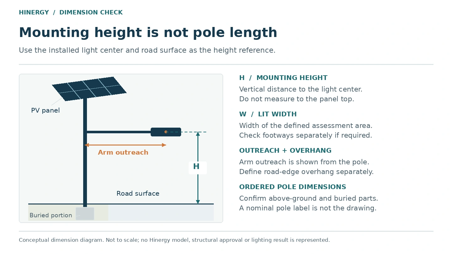
Mounting height, H: the vertical distance from the relevant road surface to the luminaire’s photometric center, or light center.
Pole dimensions: the specified pole length and height above ground; identify any buried portion and equipment above the luminaire separately.
Lit width, W: the road or other assessment area being evaluated. Sidewalks and cycle lanes may need separate assessment areas.
Setback, arm outreach, overhang and tilt: record the pole-to-road-edge distance, pole-to-light-center reach, road-edge-to-light-center overhang and luminaire angle. Show the measurement datums on the drawing.
A “6 m pole” quotation therefore needs a mounting drawing before it becomes a confirmed 6 m mounting-height input. Record dimensions in meters; 6 m is approximately 19.7 ft and 8 m is 26.2 ft.
Choose a Layout and State How Spacing Is Measured
Solar street light pole spacing must have a defined measurement convention. Compare these arrangements using the same road profile and lighting targets.
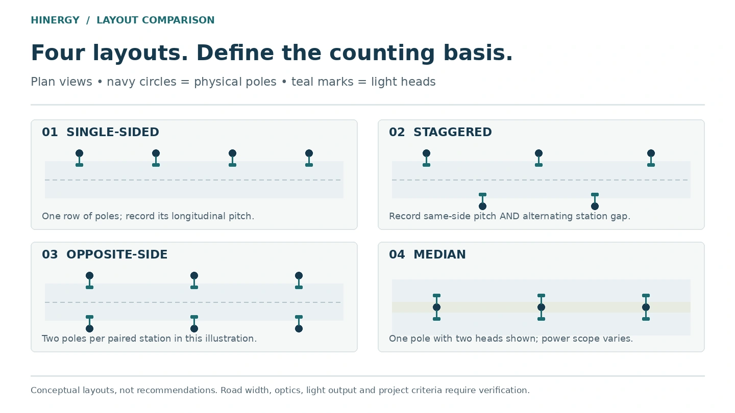
Layout | Spacing definition to record | Main question to resolve |
|---|---|---|
Single-sided street lighting | Longitudinal interval between successive poles on one side | Does the selected optic serve the far edge and spaces between poles? |
Staggered street lighting | Same-side pitch and the longitudinal gap between alternating positions | Is the quoted distance measured along one row or between successive stations? |
Opposite-side lighting | Longitudinal pitch between paired stations | Are two poles and two luminaires included at each station? |
Median lighting | Longitudinal pitch along the median | How many heads are fitted per pole, and can each carriageway be served and maintained? |
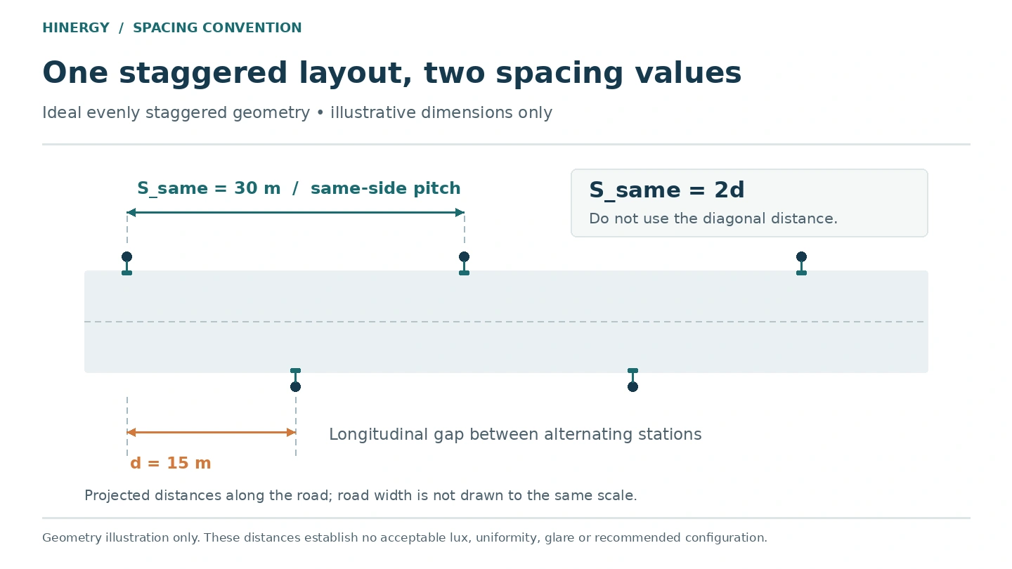
For an ideal, evenly staggered layout, a 15 m longitudinal gap between alternating positions means a 30 m same-side pitch: S_same = 2d. These are projected distances along the road, not diagonal distances across it. This arithmetic explains the drawing; it recommends no lighting configuration.
Count physical poles, light heads, panels and battery systems separately. One double-arm pole is not automatically equivalent to two independently powered solar road lights.
Use a Height and Spacing Chart as a Starting Point
A solar street light pole height and spacing chart can organize candidate arrangements. It cannot validate them without road dimensions, optics, light output and acceptance criteria. FHWA’s 2012 handbook describes height selection as a process involving geometry, photometry and lighting calculations rather than one universal formula.
| Assumed mounting height, H | Assumed spacing, S | Spacing-to-height ratio, S/H |
| 6 m | 24 m | 4.0 |
| 8 m | 24 m | 3.0 |
Solar street light height calculation and spacing calculation belong to the same design exercise. Compare candidate heights and pitches while keeping other inputs documented. Increasing height changes how the luminaire’s distribution reaches the road; increasing wattage alone cannot demonstrate that a larger gap meets every lighting criterion.
Verify the Optic and Photometric Calculation
Before accepting a solar street light DIALux simulation, establish the applicable lighting standard, edition and project class with the designer or approving authority. Road lighting and parking-area assessments may use different criteria; one average lux target is not a complete brief.
Request the IES or LDT photometric file for the exact proposed luminaire and optic, with a traceable output setting. IES identifies LM-63 as a format for transferring photometric data. A file is a calculation input, not a certificate that any installation will comply.
Check the report inputs and results
The report should identify road width, mounting height, pole pitch, arrangement, setback, overhang, tilt, luminaire quantity and maintenance assumptions. Check the calculation areas and grids against the site drawing. DIALux documentation describes road profiles, luminaire arrangements and detailed evaluation results; the project report should make those choices reviewable.
Review maintained illuminance or luminance, uniformity and glare as required by the adopted criteria. Emin/Eavg and Eavg/Emin are reciprocal ratios, so record the actual definition and limit. A maintenance factor should have an explained basis; ask whether any separate aging allowance duplicates an allowance already included.
A beam-angle footprint or overlapping light cones cannot establish minimum road illuminance. A simplified lumen-method estimate of average illuminance also cannot prove minimum values, glare performance or full compliance. If a quotation changes the optic, output or geometry, request a revised calculation.
Keep the Solar Energy and Dimming Plan Consistent
At the same light output, optical distribution and installed geometry, solar power does not inherently require a different pole spacing. The additional question is whether the energy system can sustain the light-output schedule used in the layout assessment.
Check seasonal solar input, panel orientation, shading, usable battery energy and recovery assumptions against the hourly load. Include CCTV or communications loads over their actual operating periods. JRC’s PVGIS guidance explains how off-grid calculations account for consumption profiles and battery operation; annual energy totals alone can conceal periods of shortfall.
Review any approved dimmed stage against its required lighting criteria. A controller’s “50%” command does not by itself establish 50% electrical consumption or adequate road lighting. For the wider document checklist, see our solar street light specifications guide.
Check Whether the Layout Can Be Installed and Maintained
Overlay the proposed solar street light installation spacing on the actual site plan. Check junctions, crossings, curves, changes in level, entrances, trees, utilities and available roadside space. Adjusted pole positions need corresponding lighting checks, particularly where a regular straight-road pattern no longer applies.
Review the complete assembly’s wind loading, panel area, brackets, foundation interfaces and corrosion exposure. Pole height alone does not establish structural suitability. Foundation details depend on the assembly, ground conditions and applicable local requirements; a generic foundation depth is not a project design.
Confirm access for panel cleaning, battery replacement and luminaire servicing. Independent panel positioning may change both shading and access arrangements. Our all-in-one vs split solar street light comparison explains those structural choices without treating them as proof of lighting performance.
Prepare a Project Checklist Before Comparing Quotations
Give each solar street light manufacturer or supplier the same brief. For commercial solar street lights, compare the complete installation and service scope alongside the equipment price.
Check | Why it matters | What to provide or verify |
|---|---|---|
Location and road geometry | Establishes the design setting | Coordinates, scaled plan, road width, footways, slopes and obstructions |
Lighting criteria | Defines acceptance | Adopted standard/edition, class, maintained targets, uniformity definition and glare criteria |
Heights and interfaces | Prevents dimensional ambiguity | Mounting height, pole drawing, setback, overhang, tilt and existing-pole details |
Layout and quantities | Makes bids comparable | Spacing convention, station locations, poles, heads and complete power-system quantities |
Photometric evidence | Connects the offer to predicted performance | Matched IES/LDT file, configuration identity and calculation report with assumptions |
Solar operating plan | Connects lighting duty to energy supply | Hourly schedule, approved dimming, seasonal assumptions, reserve and additional loads |
Installation and service | Defines practical responsibility | Structural review, foundation scope, access, spares and component-replacement arrangements |
Supply and delivery | Prevents omissions from the quote | Quantity, destination, packaging, installation scope and required documents |
Suggested RFQ wording
Use the approved layout to compare poles, foundations, transport, lifting and later service costs. A lower pole count can reduce some costs, but longer spans may alter equipment and performance requirements; confirm the complete proposal before treating the saving as real.
Frequently Asked Questions
How far apart should solar street light poles be?
There is no universal distance between solar street light poles. Establish a candidate layout, then verify the proposed luminaire against the road geometry, maintained lighting criteria and site constraints. State exactly which interval the quoted distance describes.
What spacing should I use for a 6 m or 8 m solar street light pole?
Does a taller pole always allow wider spacing?
Can a solar street light spacing calculator replace a DIALux report?
Can existing poles be reused for solar LED street lighting?